DIY Yagi Antenna Guide: Build Your Own For Ham Radio!
Is it possible to build a high-performance antenna without breaking the bank or requiring a degree in electrical engineering? The answer is a resounding yes, and the Yagi antenna, in its DIY form, is a testament to that fact.
The world of radio communication often seems shrouded in complex terminology and expensive equipment. However, the Yagi antenna, a staple in amateur radio and other applications, presents an accessible entry point for enthusiasts and those seeking a practical, high-gain antenna solution. This article delves into the realm of DIY Yagi antennas, exploring their construction, functionality, and the benefits they offer. We will unravel the mysteries of this versatile antenna, demonstrating that achieving superior performance is within reach for anyone with a little time, basic tools, and a willingness to learn.
Before delving into the specifics of construction, it is important to define what a Yagi antenna is and what it is used for. The term "Yagi" is a tribute to Japanese antenna experts, Hidetsugu Yagi and Shintaro Uda, who pioneered its design. Primarily, a Yagi antenna is a directional antenna, meaning it concentrates radio waves in a specific direction, thereby enhancing signal strength in that direction while reducing interference from other directions. This directional characteristic makes Yagi antennas ideal for applications such as point-to-point communication, receiving weak signals, and mitigating interference in crowded radio environments. Yagi antennas are popular for amateur radios, TVs, and internet modems. The construction is based on metal rods of varying lengths and quantities.
- Matt Rifes Age Birthday More What You Need To Know
- Elena Moussa Height Weight Body Stats What You Need To Know
The beauty of the Yagi antenna lies in its simplicity of design, making it suitable for DIY projects. The core components of a Yagi antenna consist of three essential elements: the driven element, the reflector, and the director(s). The driven element is the component connected to the radio and receives or transmits the signal. The reflector, typically longer than the driven element, is positioned behind the driven element and reflects radio waves forward, further concentrating the signal. Directors, shorter than the driven element, are positioned in front of the driven element, further focusing the signal in the desired direction. The number of directors determines the antenna's gain and directivity; more directors generally mean higher gain and sharper directionality.
For those looking to build their own Yagi antenna, there are plenty of plans available online, making it easier than ever to get started. While many resources offer detailed schematics and instructions, a good step-by-step video can often make the process more accessible. The DIY approach provides a gratifying hands-on experience and allows for customization based on specific needs and available materials.
Building a Yagi antenna is, in essence, a rewarding journey into the fundamentals of radio technology. You actually have to use it on the air to get a feel of how it performs. While the theoretical aspects are interesting, the real value lies in applying them to build a functional antenna that enhances communication capabilities. Those work ok on 2 m but on 70 cm the radiation pattern is terrible.
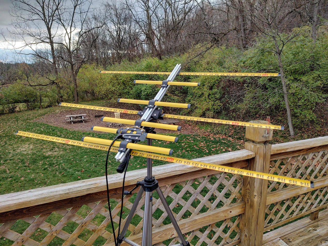
Several applications on the internet have been developed to design Yagi antennas. A Yagi antenna has three types of elements, consisting of metal rods of varying lengths and quantities. For this tutorial, a design for 1.3 GHz will be explained. This antenna project provides good performance because you build it exactly for the single TV channel or frequency you want to receive. In this publication, a very light weight, cheap, easy to build and deployable in 30 seconds portable VHF antenna for the 2-meter band will be explained.
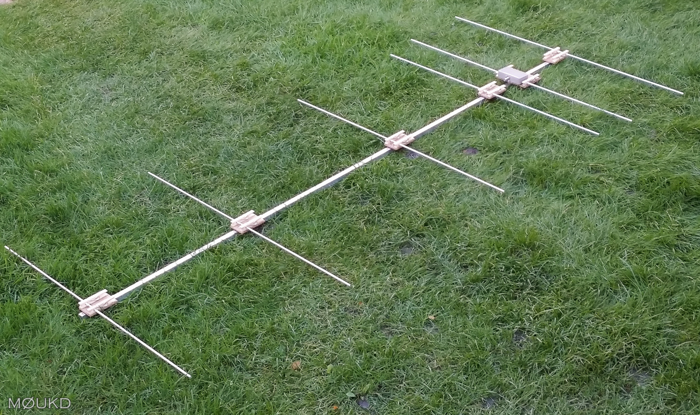
The first step in building a Yagi antenna is to determine the operating frequency. Whether targeting the 2-meter amateur radio band (144-148 MHz) or the 70 cm band (430-440 MHz), the frequency dictates the dimensions of the antenna's elements. Several online calculators and design tools are available to assist in this process. These tools take into account the operating frequency, boom diameter, element diameter, and the desired number of directors. Then, the elements are cut to the calculated lengths. For instance, building a Yagi antenna designed for 2-meter and 70 cm ham radio bands, it can be used to communicate with amateur radio satellites or to assist in getting into that repeater that is just a little too far away. The antenna is constructed from M4 stainless steel threaded rods. As they are relatively inexpensive and commonplace at most DIY stores. Additionally, it is an easy material to work with and does not require any special tooling.
The driven element is typically a dipole antenna, constructed from a length of wire or a metal rod cut to a specific length based on the operating frequency. The reflector, which is placed behind the driven element, is usually slightly longer than the driven element. The directors, placed in front of the driven element, are slightly shorter. The configuration of this yagi antenna is known as a plumbers delight (everything is connected together and grounded), a gamma match will be the simplest to construct. The gamma tube is usually ~10% of the length of the driven element, in this case it will be 5 long and made from a length of 0.155 diameter brass hobby tubing.
The next step involves constructing the boom, the structural backbone of the Yagi antenna. The boom is a non-conductive support to which all the elements are mounted. Suitable materials for the boom include PVC pipe, wood, or any other non-conductive material. The elements are then attached to the boom, ensuring they are positioned at the correct spacing and aligned precisely. The driven element is connected to the radio via coaxial cable, completing the electrical connection.
The design and construction of a Yagi antenna involve a bit of theory, which is best presented by understanding the role of each element. When you build an antenna from a patterned design, you really cannot predict how it will behave in real life. An antenna analyzer doesnt give you the whole picture either. The driven element resonates at the desired frequency, and the reflector and directors influence the antenna's radiation pattern. By manipulating the dimensions and spacing of these elements, the antenna's performance can be tuned. For example, increasing the number of directors can increase the gain, resulting in a more focused and powerful signal.
For a straightforward DIY approach, many builders opt for a "plumber's delight" configuration, where all elements are directly connected to the boom and grounded. An alternative is to make a 2 m dipole with one (or two) closely spaced (about 1 inch) 70 cm 1/2 wave parasitic element (also called a coupled resonator). This design simplifies the construction process. In this case, a gamma match will be the simplest to construct.
Once the antenna is assembled, testing is crucial to ensure its optimal performance. The antennas work extremely well. Using a Standing Wave Ratio (SWR) meter will help to verify the antenna's match to the radio. The s11 or SWR measurement results are also provided. Fine-tuning the antenna might involve adjusting the element lengths or the spacing. When the antenna is ready to test, it is important to have a listen. The antenna can be cranked up into position at 35 feet.
Several factors can influence the performance of a DIY Yagi antenna. Element dimensions and spacing are critical, as deviations can affect the antenna's resonance and directional characteristics. In this publication, you can build a very light weight, cheap, easy to build and deployable in 30 seconds portable VHF antenna for the 2 meter band. The boom material and construction also affect the antenna's rigidity and stability. The environment can also play a role; obstacles such as buildings or trees can obstruct the signal path and reduce the antenna's effectiveness. That must be the reason this antenna showing lesser speed than a biquad antenna.
The Yagi antenna, with its directional properties and gain, has a wide range of applications. It is perfect to use for fox hunts or as a portable directional antenna for public service events. It can be used to communicate with amateur radio satellites or to assist in getting into that repeater that is just a little too far away. It is a popular choice for receiving television signals, improving internet modem signals, and enhancing communication in amateur radio. As a design, it is the simplest there is: a 4 element 50-ohm Yagi with a 2.20m boom. A better design is to make a 2 m dipole with one (or two) closely spaced (about 1 inch) 70 cm 1/2 wave parasitic element (also called a coupled resonator).
Despite the numerous online resources and tutorials, building a Yagi antenna is not without its challenges. Some may find it difficult to calculate the precise element lengths and spacing. When working with a patterned design, it is difficult to predict how it will behave in real life. Even with the best tools, the antenna might not perform as expected, requiring further adjustments. Patience and perseverance are key ingredients for success. And, finally, a Yagi antenna has three types of elements, consisting of metal rods of varying lengths and quantities.
The DIY Yagi antenna is a testament to the power of hands-on learning and the ability to build something functional with a little effort. It allows hobbyists and enthusiasts to delve into the world of radio technology and create an antenna that is tailored to their specific needs. The Yagi antenna is a powerful high-gain directional antenna. This is how to build a Yagi antenna article for the DIY Yagi antenna for the 433 MHz production process of the homemade Yagi antenna. The antenna is constructed from M4 stainless steel threaded rods, as they are relatively inexpensive and common at most DIY stores. Additionally, it is an easy material to work with and does not require any special tooling.
The Yagi antenna is more than just a piece of equipment; it represents a journey of learning and discovery. It is a rewarding endeavor. Whether using it for amateur radio, receiving TV signals, or experimenting with wireless communication, the DIY Yagi antenna offers a unique opportunity to gain valuable skills. When you build an antenna from a patterned design, you really cannot predict how it will behave in real life. There are several applications on the internet to design Yagi antennas. So, watch the video and go ahead and build your own tape measure Yagi.

Detail Author:
- Name : Isaac Pfeffer
- Username : wkreiger
- Email : brook26@hotmail.com
- Birthdate : 1989-09-21
- Address : 736 Kutch Rest Apt. 313 Port Jacintoburgh, WI 52643-4160
- Phone : (240) 490-4702
- Company : Lubowitz LLC
- Job : Manufacturing Sales Representative
- Bio : Eius accusamus quas nihil molestiae qui similique. Nostrum dolores earum facere autem qui quas facere voluptatum. Vel accusamus nisi non iste in maxime. Rem quaerat voluptatem sunt quidem ipsa aut.
Socials
tiktok:
- url : https://tiktok.com/@nicholas.torphy
- username : nicholas.torphy
- bio : Impedit quaerat similique in.
- followers : 5121
- following : 630
twitter:
- url : https://twitter.com/nicholas.torphy
- username : nicholas.torphy
- bio : Dolor rerum minus quo fuga necessitatibus. Facere aspernatur vero est vel. Aut omnis et voluptas magni repudiandae hic deserunt non.
- followers : 5864
- following : 2416
linkedin:
- url : https://linkedin.com/in/nicholas.torphy
- username : nicholas.torphy
- bio : Impedit qui nobis adipisci quisquam.
- followers : 3101
- following : 2735
facebook:
- url : https://facebook.com/ntorphy
- username : ntorphy
- bio : Illo voluptas et debitis sed ad voluptatem quidem.
- followers : 1119
- following : 65
